The design of acoustooptic tunable filters is one of the most discussed problems in present acoustooptics because of a very wide area of the application of these devices in quantum electronics, spectrometry and spectropolarimetry, fluorescence spectroscopy, spectral imaging , telecommunication etc.
The principle of operation of the filters is based on the dependence of the diffracted light wavelength on the acoustic frequency. There are two types of the acoustooptic filters – collinear and non-collinear filters – depending on geometry of acoustooptic interaction. Here we consider only non-collinear filters based on the TeO2 single crystal. A basic geometry of the acoustooptic interaction in the filter is shown in Fig. 1f. The polarization of the incident light can be either ordinary or extraordinary. For the definition, we assume ordinary polarization. Here the following system of symbols is used:
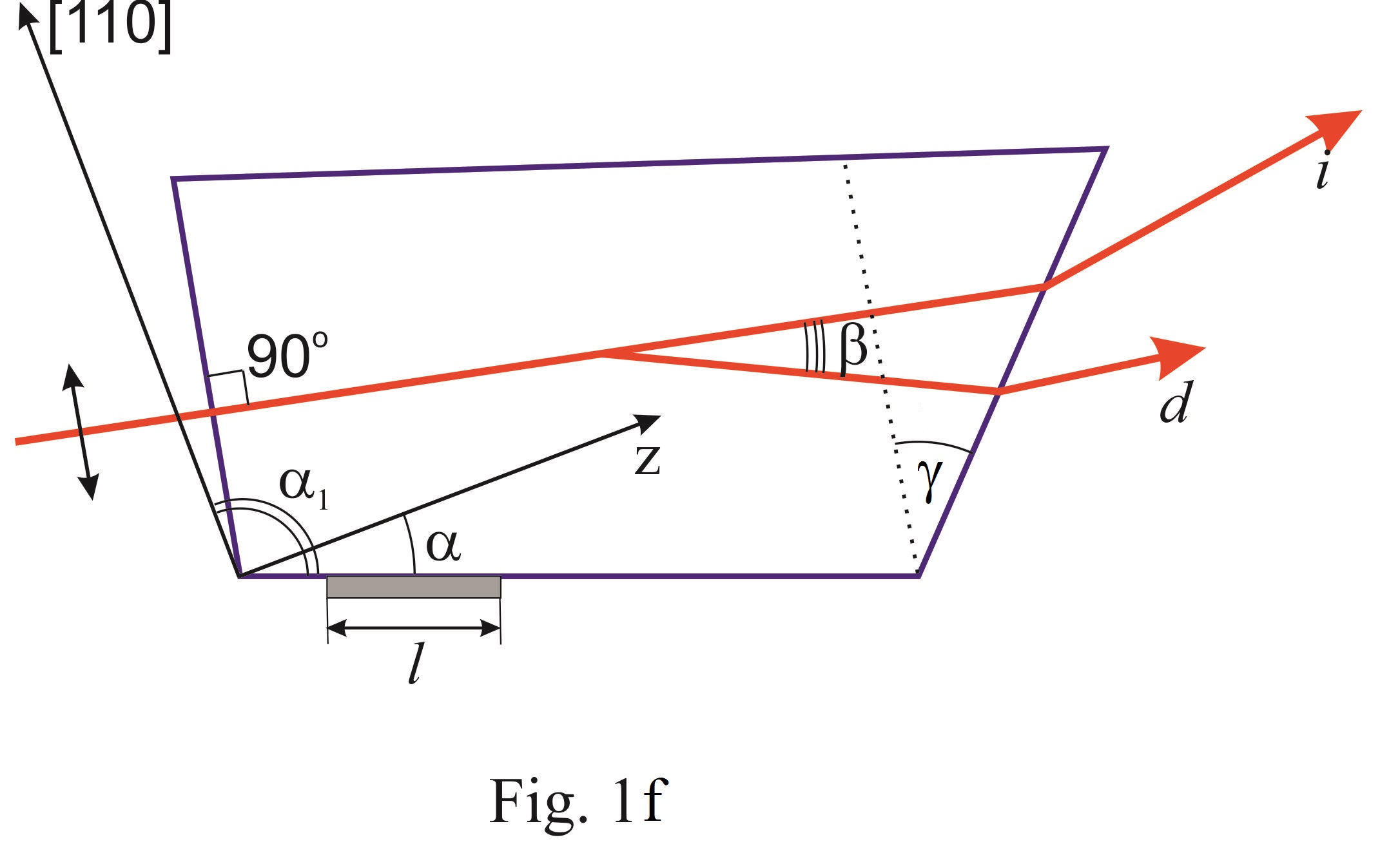
 is the angle between the acoustic wave vector and the crystallographic axis Z of the crystal;
 is the wedge angle between the input and output faces of the filter cell (the wedge angle is necessary for eliminating the angular shift of the diffracted beam caused by frequency changing);
 is the angle between the incident light wave vector and [110] axis of the crystal;
 is the angle between the input face of the cell and acoustic wave vector;
 is the angle between deflected and non-deflected light at the central frequency;
 is the transducer length.
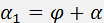
The incidence angle and the central frequency  of the filter are defined by the following set of equations:
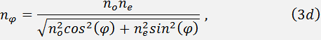


Eqs. (4d) and (5d) correspond to the geometry presented in Fig. 1f, respectively. Indices of refraction for ordinary  and extraordinary
  polarized beams are determined with taking into account their dispersive dependence.
The sound velocity  depends on the angle as:
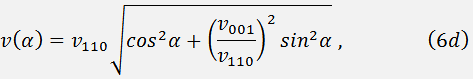
where  and
and  are the sound velocities along the axes [110] and [001], correspondingly. The value is determined by the angles and
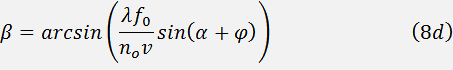
The angle between the diffracted and non-diffracted beams defines the view field of the filter; it can be calculated from the formula
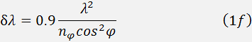
Basic parameters of the filter are spectral resolution  and spectral tuning band
  . The spectral resolution at 3 dB level is determined from the expression:
The tuning band is defines by the frequency band of the transducer. As a rule, the band does not exceed octave, especially in UV region of the spectrum.