AO deflectors
Optical deflectors are intended for spatial controlling optical beams. The functioning of the acoustooptic deflectors is based on the dependence of the diffraction angle  on the acoustic frequency
: varying the frequency in the range
on the acoustic frequency
: varying the frequency in the range  produces changing the diffraction angle in the range
where is the optical wavelength, is the acoustic velocity.
The most important characteristic of the deflector is its resolution which is understood as a number of spatially resolved light elements (spots) kept within the scanning line. Thus, one can define the number of resolved
elements as a ratio of the scanning angle  to the angular width of the scanning beam
  :
:
 . The divergence of the diffracted beam depends on the distribution of the incident light intensity over the acoustooptic cell aperture, as well as on the
resolution criterion. It is a common practice to use the Rayleigh criterion, according to which two spots of equal intensity are considered resolved, if the total intensity between the two spots is 81% of that at the centres of the spots. In this case
, where is the linear optical aperture in the acoustooptic interaction plane. As a result, one can yield the following expression:
. The divergence of the diffracted beam depends on the distribution of the incident light intensity over the acoustooptic cell aperture, as well as on the
resolution criterion. It is a common practice to use the Rayleigh criterion, according to which two spots of equal intensity are considered resolved, if the total intensity between the two spots is 81% of that at the centres of the spots. In this case
, where is the linear optical aperture in the acoustooptic interaction plane. As a result, one can yield the following expression:
This relationship shows that for a given material the resolution is proportional to the cell aperture and to the acoustic frequency bandwidth. The parameter  determines the time required for the ultrasound to cross the optical beam. In essence,
  is the switching time or the response time of the device upon a discrete change of the sound frequency.
Below we consider acousto-optic deflectors based on TeO2 single crystals. Such deflectors employ so-called anisotropic diffraction of light. This type of acoustooptic interaction is much more complicated than isotropic diffraction. A number of deflector parameters cannot be found in analytical formulae and arduous numerical calculations are required.
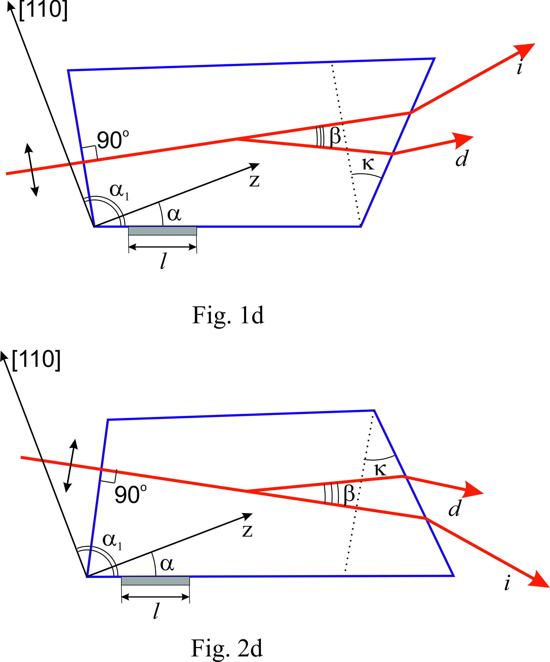
The basic geometry of the acoustooptic deflector is presented in Figs 1d and 2d. The geometry shown in Fig. 1d is more preferable for the visible region, whereas the geometry displayed in Fig. 2d is more suitable for the infrared region. Polarization of the incident light is shown in the figures. Here the following system of symbols is used:
 is the angle between the acoustic wave vector and the crystallographic axis Z of the crystal;
 is the wedge angle between the input and output faces of the deflector cell (the wedge angle is necessary for to keep the direction of the scanning beam at the central frequency collinearly to the direction of the incident beam);
 is the angle between the incident light wave vector and [110] axis of the crystal;
 is the angle between the input face of the cell and acoustic wave vector;
 is the angle between deflected and non-deflected light at the central frequency;
 is the transducer length.
The incidence angle and the central frequency  of the deflector are defined by the following set of equations:
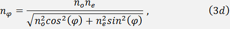


Eqs. (4d) and (5d) correspond to the geometry presented in Figs 1d 2d, respectively. Indices of refraction for ordinary  and extraordinary
  polarized beams are determined with taking into account their dispersive dependence.
The sound velocity  depends on the angle as:
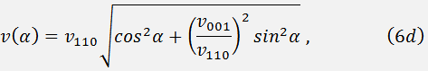
where  and
and  are the sound velocities along the axes [110] and [001], correspondingly. The value is determined by the angles and
The wedge angle can be found from the expression:
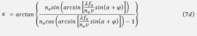
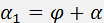
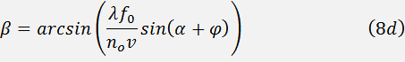
The angle is defined from the formula:
Here we present characteristics of acousto-optic deflectors for major laser wavelength 488 nm, 515 nm, 532 nm, 633 nm and 1064 nm, 1550 nm (Fig. 2d).
For the definition, we have chosen the central frequency of all the deflectors constant and equal to 80 MHz. The transducer length corresponds to the operating frequency band of the deflector equal to 35 MHz at 1.5 dB level. The transducer height is defined by the laser beam diameter d.
 , nm , nm | 488 | 515 | 532 | 633 | 1064 | 1300 | 1550 |
|---|---|---|---|---|---|---|---|
| , deg | 85.80 | 85.58 | 85.42 | 84.52 | 80.22 | 78.23 | 76.25 |
| , MHz | 80 | 80 | 80 | 80 | 80 | 80 | 80 |
| , deg. | 5.63 | 5.98 | 6.2 | 7.4 | 6.44 | 7.77 | 9.07 |
| , deg. | 2.6 | 2.77 | 2.87 | 3.45 | 6.14 | 7.38 | 8.58 |
| , deg. | 1.5 | 1.57 | 1.62 | 1.92 | 3.36 | 4.03 | 4.67 |